Soldering
GyroCycle requires you to solder a few wires together to properly work. Below is a description of what cables need to be soldered where.
Diagrams are provided below for easier reference, but you can also directly look at the electrical schema. Be warned though, not all connections on the electrical schema need to be soldered.
| Description | Download link |
|---|---|
Electrical Schema (.pdf) | Download |
Electrical Schema (.zip Kicad project) | Download |
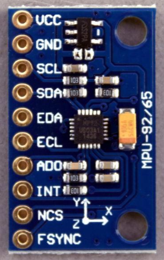
Soldering to the MPU6050
You will need to solder five female connectors to the MPU6050 sensor. A length of approximately 10 centimeters is fine for those. The wires need to be connected to
VCCGNDSCLSDAINT
Soldering the LIPO protection circuit and power supply wires
To prepare the power-supply setup of the bicycle, refer to the schema below. Blue circles indicate where a solder is needed.
INFO
A part of the schema is dedicated to the On-Off switch of the circuit. We recommend you add one, however the way to solder it might defer depending on which one you got.
WARNING
Make sure to use thick enough cables for the powered supplied from the battery and from the LIPO protection board.
Make sure to also check the 3D printed pieces (next page of the guide) for the LIPO protection board. After soldering, printing and assembling, you should obtain something similar to the following:
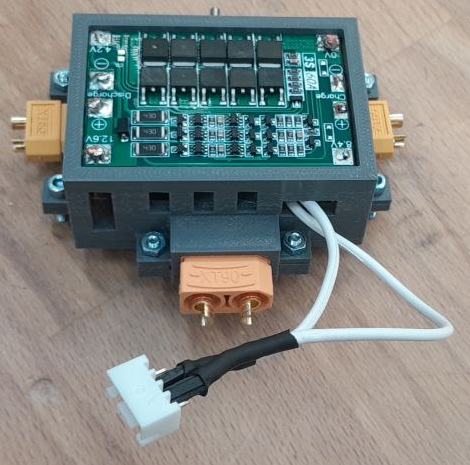
Plan the length of your cables accordingly.
Here is the diagram to help you with soldering:

Once all soldering has been done, we can move on to laser-cutting some parts.